Home > Electronics > Fidget Spinner
Fidget Spinner
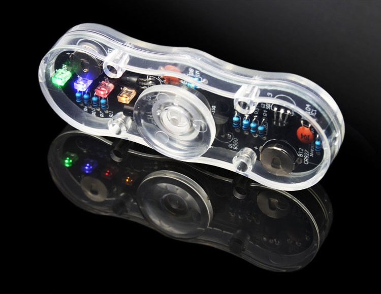
The fidget spinner circuit causes the LEDs to switch on and off rapidly. How fast, well too fast to see while the spinner is still, but if you spin it then you'll see the pattern as the lights switch on and off.
The circuit is constructed on a small printed circuit board that fits inside a clear plastic case. In the centre is a ball bearing and two plastic cups that fit into the bearing. The circuit is laid out in such a way to balance the weight when it rotates about the central axis.

Circuit Diagram
This circuit is called an astable multivibrator. The fidget spinner circuit alternates between two states. Each state corresponds to one pair of LEDs being switched on and the other off. There's a really good simulator showing this type of circuit at falstad.com that shows the way the current and voltage changes.

Assembling the kit
These are photos showing the Fidget Spinner circuit board being assembled and in operation.
The circuit board is silk screened with the outline and value of each component.
The components are:
| Item | Quantity | Function / Description |
|---|---|---|
| Transistor | 3 | 9013 |
| Transistor | 1 | 8550 |
| Resistor | 5 | 1k Ohm |
| Resistor | 3 | 10k Ohm |
| Resistor | 3 | 1M Ohm |
| Capacitor | 3 | 0.1uF |
| LED | 4 | Blue, green, orange, red |
| Battery | 2 | CR927 |
| Switch | 1 | press button |
When assembling the circuit take note of the space between the circuit board and the case. The LEDs need to be fitted flush to the circuit board, and the capacitors and transistors need to be bent over flat onto the board before soldering into place. A 1mm dot of blue tac can be used to hold the switch while it's soldered in place.
The longer lead on the LED goes in the hole marked with a + It doesn't matter too much which position each coloured LED goes in.
The original kit was obtained from AliExpress.
